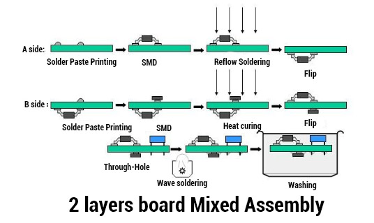
Surface Mount Assembly Process
Originally, all PCBs were assembled by hand using only a solder iron. As technology progresses, components get smaller and more difficult to assemble by hand and the amount of components that may fit on a single board increases. Thus the need for auto assembly was developed.

Required Elements
The following are the required elements for auto assembly:
-
- Gerbers in 274-X (embedded apertures) including fabrication drawing.
- Part centroid text file with Reference Designators, external placement layer, and X & Y location and rotation in ASCII format.
- Numerical control (NC) drill files
- Solder paste file (one of the Gerber files) for all sides mounted
- Glue dot file
- If possible, the design database, specifying the database format (program name)
- Parts list or BOM (bill of material)
- Parts or hardware required
The Gerber files define the pad locations, help the assembly house determine where pin 1 is located, and provide a heads-up of how the board looks. The database can also be used to determine the location of pin 1. Some board houses choose to make their own solder-paste file/stencil. The designer may create the solder paste file to his/her preference with experience.
It is good to learn how and why the assembly house makes and duplicates its stencils to ensure consistency from each assembly house (the common name for any company that assembles boards). The solder paste file is used to mask the entire board except those areas that will be soldered. Solder paste is applied to the exposed pads and the stencil is removed. Components are applied and held to the board by the solder paste and the glue dots securing the components as they are soldered to the board.
For component placement
This process requires part placement/centroid file is required to know where the center of the part is. The layer ID shows what side the part is placed on, and the rotation displays the orientation of the component.
Consistency in rotation of the original component is critical to report. Unless the designer’s software can account for inconsistencies, all components should be created in the same orientation.
NC drill files are used to locate mounting holes and provide the hole sizes for thru-hole components. This also allows the assembly house to determine adequate clearance for the component lead.
A bill of material or parts list (BOM) is used to reference the designators of the centroid file and the components that need to be mounted. The BOM should also provide information on whether the component is an SM or a thru-hole component.
Other Considerations
Other considerations for auto assembly are the board size, the panel size, and breakaways. The boards are commonly assembled in a panel that may contain many boards. The panel is the original material that the boards were etched in. The panels pass to the assembly house with all boards intact.
Note
Breakaways are the connections around a board that hold the board during assembly but can be broken easily when it is time to remove the board.
1. Ordering a Board
InvoPCBA One-Stop Solution for PCB & Prototype Assembly,
2 .DFM Check
The DFM check looks at all the design specifications of a PCB. Specifically, this check looks for any missing, redundant or potentially problematic features. Any of these issues may severely and negatively influence the functionality of the final project. For example, one common PCB design flaw is leaving too little spacing between PCB components. This can result in shorts and other malfunctions.
By identifying potential problems before manufacturing begins, DFM checks can cut manufacturing costs and eliminate unforeseen expenses. This is because these checks cut down on the number of scrapped boards. As part of our commitment to quality at a low cost.


