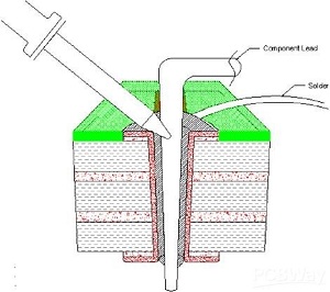
In electronics, through-hole assembly is the process of mounting leaded components onto a PCB, which involves drilling through holes. Subsequently, the components are soldered onto the pads on the opposite side of the circuit board, either manually or using an automated soldering machine. The proportion of solder flux is carefully determined as it plays a crucial role in maintaining the quality of solder joints between the pads and component leads. During the through-hole assembly process, component leads are inserted through drilled holes from the top of the board to the bottom and then soldered. These drilled holes can be plated through-holes (PTH) or non-plated through-holes (NPTH).
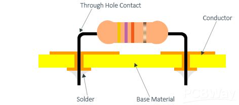
Types of Through-hole Component Types
Through-hole assembly technology has two main types of components: axial and radial components, as well as DIP components.
Axial components: Axial leaded components are a type of through-hole electronic component packaging. Axial leads pass straight through the component, with the wire leads connected to the component at each end.
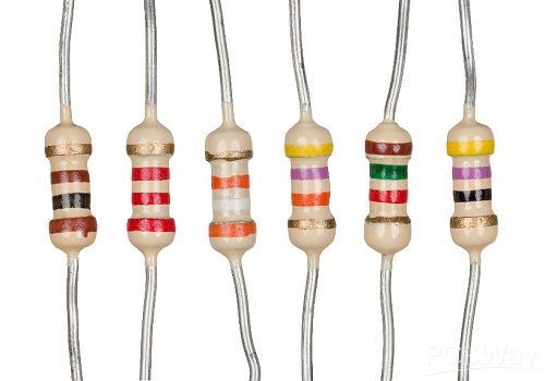
Samples of Axial Components:
- Through-hole capacitor
- Through-hole resistor
- Through-hole diode
- Through-hole inductor
Radial components: Radial leads are also a type of through-hole electronic component packaging. Radial leads are placed parallel to the surface of the component. When radial leads and their components are placed on the circuit board, they are oriented perpendicular to the board, occupying less space, making them highly useful in high-density applications.
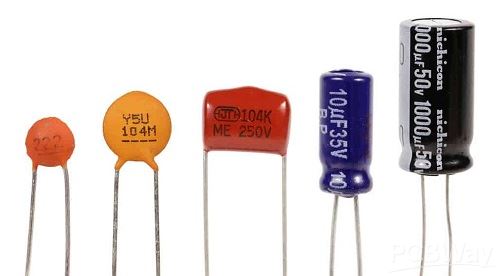
Samples of Radial Components:
- Aluminum electrolytic capacitor
- Through-hole ceramic capacitor
- Photoresistor
- Fuse
- Light-emitting diode (LED)
- Field-effect transistor (FET)
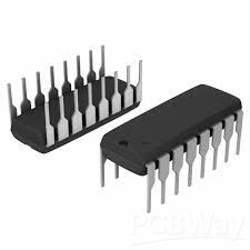
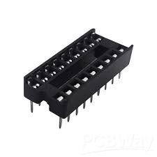
DIP components: DIP is commonly used as a package for various chips. It is typically installed using an IC socket, and sometimes directly mounted on the board.
Steps in soldering a thru-hole component:
Figures 1-1 through 1-4 display the general steps in soldering a thru-hole component. In step 1, the hole and pad to be soldered are prepared, with the lead being placed into/through the hole. The lead should be placed in such a way as to keep the bend above the soldered area, reducing heat and solder requirements.
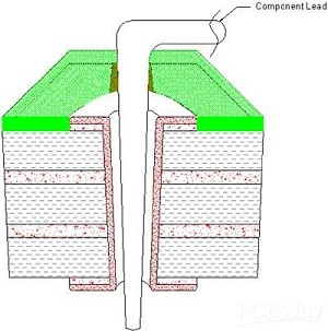
Figure 1-1. Hole and pad to be soldered—step 1
In step 2, heat is applied evenly to the lead and the pad/hole, heating the material so the solder will adhere to both surfaces.
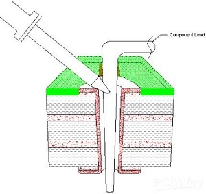
Figure 1-2. Applying heat evenly to the lead and the pad/hole—step 2
In step 3, the solder contacts the end of the iron, which causes the solder to change into a liquid and flow into the hole.
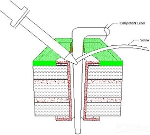
Figure 1-3. Contacting the end of the iron—step 3.
In step 4, the solder flows through the hole, creating a mound on both the bottom and topside. Since this lead was soldered from the topside, the bottom side should be inspected for adequate solder and joint quality. Some assembly may require solder from both sides to ensure quality. Adequate clearance inside the hole allows good solder flow through the board, allowing only one side to have solder applied. Tight clearances may require soldering on both sides, increasing soldering time.
